BIM Plan to Execute: Adding Tunnel/Road Capacity to Existing Thimble Shoal Tunnel

This article presents the initial planning, pre-execution, and execution stages of a BIM-driven project to create a new two-lane tunnel under Thimble Shoal Channel. When complete, the new tunnel will carry two lanes of traffic southbound and the existing tunnel will carry two lanes of traffic northbound.
The project design is quite a challenge, as it’s meant to connect to an existing highway and tunnel system in such a way so as not to disturb the flow of traffic during construction. Using Civil 3D, Revit, Navisworks, and additional Autodesk software, we were able maximize our use of the model data, not just for construction documents but also for analysis. Coordination of not just the design data, but also the various teams and interests on the project were integral to making it successful.
BIM Execution Planning
Key Project Challenges
a. Adding highway capacity to existing Thimble Shoal Tunnel.
b. Designing additional tunnel and road capacity, keeping in mind that construction can not interfere with existing tunnel operations.
c. Coordinating design and construction with multiple offices and consultants.
d. A tight schedule.
Key Technical Challenges
a. Needing to accommodate different skill sets and capabilities amongst project team members and consultants.
b. Starting the BIM execution planning and modeling, right after the pre-design stage.
c. Working with large geotechnical datasets for borehole analysis along tunnel length.
d. Coordinating design and construction with multiple offices and consultants
Where to Begin
We began the planning by looking at the scope of work and contract details to get an overall view of the total extent of the project. From there we worked with individual team members and managers to get an idea of the amount and type of structures that are being proposed or are existing, as well as the services needed to be provided to each.
I also like to get any existing renderings, project descriptions, site photos, and other types of identifying information from the proposal stage, as to help more conceptualize the entire project. Care must be taken to not use out of date material of course.

We then started to fill out our BIM execution plan template in as much detail as possible. We used an amended BIM execution plan template that was a combination of existing resources from Penn State, the Army Corp of Engineers, as well as prior Mott MacDonald projects. The plan included the following:
- Project Information
- Contacts, Roles, and Responsibilities
- Goals and Uses
- Data Exchange
- Technological Infrastructure
- Collaboration Procedures and Resources
- Project Information
- BIM/CAD Planning
- Analysis
- Quality Control
- Archiving
- Supplemental Documents
Project Information
Most of the project information as it was filled in on the BIM execution was gathered from the engineering services agreement. While important to fill in the information as much as possible, we decided to keep the amount of overall information to a minimum, as we did not want to duplicate information that was kept elsewhere, or run the risk of information not being up to date.
Key Points: Project Information
a. Use centralized source
b. Keep it concise
c. Think like the person reading it
d. Keep it precise
e. Avoid placeholder info
f. Avoid dated information that is sourced elsewhere
Contacts, Roles, and Responsibilities
We had contact list information from the very beginning of the project contained within the project execution plan, making filling in information about the engineers and managers easy. The challenge was to correctly identify the staff that would be doing production work and matching them up with an associated BIM role on the project, as we had multiple disciplines participating, some in different offices. This was where it was important for us to have designated local resources within each office, for example local office BIM/CAD managers, who could help us to identify the proper staff.
Over the course of the project the list of contacts also had to stay malleable, as we brought on additional consultants and internal project team members. The roles definitions we put in place were taken from internal definitions that Mott MacDonald had put in place for BIM projects. These roles and their definitions, once the kick off meeting took place, were properly explained to the management staff, and described within the BIM execution plan.
Key Points: Contacts, Roles, and Responsibilities
a. Use well-defined roles
b. Define role assignments as soon as possible
c. Some staff will serve in multiple roles
d. Explain the reason for the roles to management
Goals and Uses
The goals and uses were gleaned from team discussions and discovery of bid, pre-design materials available. With a project of this size, potential goals and uses were discussed as much as possible up front, but we did happen to come across new uses for the model as the project progressed.
Guiding the projects managers in the understanding of what BIM is from a functional standpoint, versus a higher level what they may have seen in presentations, gave them a better understanding of what the models could be potentially used for.
Key Points: Goals and Uses
a. Use well defined goals and uses
b. Check for existing corporate definitions
c. Look for additional areas of use
d. Work with engineers to explain the functional benefits of BIM
Data Exchange
For us, defining the schedule for data exchange was kept as a moving target, because the project schedule tended to be in flux, due to its complex nature. For most of the project, we modeled to the level of detail required for contract drawings and some scheduling when feasible, with exceptions for space proofing in areas of concern or areas where visual analysis was important.
Key Points: Data Exchange
a. Be flexible with the upfront data exchange dates
b. Try to keep the level of detail in line with your BIM goals and uses
c. Identify key areas for additional detail
Technological Infrastructure
Here’s where we tried to nail down the software we were using and the hardware required to run said software. This portion of the planning was done in hand with our IT department. We can get automated reports of all staff software and hardware. We then used these reports as well as discussions with staff to find areas we needed to upgrade.
Software
All staff members had to use the same software and versions not just across the project team, but also amongst sub-consultants. Most of our staff on the project has prior Autodesk software experience.
We used 2016 versions of Civil 3D, Revit, Navisworks, Robot Structural and 3ds Max. Standardizing on the same types and versions of Autodesk software made it much easier to share data without a great deal of data conversion or manipulation needed. Try to include a note or contact for updating the software as needed during the project. As the project data sets grow larger, issues with the software may necessitate the installation of pending service packs. We tried to mitigate interruptive service pack updates, by having our IT install the latest service packs whenever a new software was installed. Announcements of new services packs were made during our weekly BIM/CAD call.
Key Points: Software
a. Keep everyone’s software up to date with the latest service pack, scheduling installations so no one has a different build of software.
b. Make it clear that any drafters/modelers/consultants brought into the project should have the software required installed with the last softer service pack installed per direction from the BIM/CAD manager.
Hardware
Once we had settled on a software version, we were ready to start looking at any additional hardware that may be required. We looked at the recommended hardware requirements from Autodesk’s web site to create a baseline hardware profile for staff that would be doing modeling. We then used our reporting capabilities to look at the existing hardware on all potential modelers computers. As most of the staff has done at least one BIM project, we can minimize additional hardware purchases as much as possible.
Key Points: Hardware
a. Do a hardware and software review
b. Work with IT in the earliest planning stages
c. Standardized versions of all software
d. Set up a service pack schedule
e. Make the argument for hardware, based on fact
Collaboration Procedures and Resources
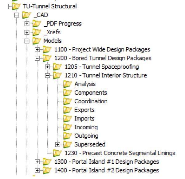
This is the area where we outline the collaboration systems and processes that will be used for managing modeling data. Here we begin to define the environment within which the data will reside. We used a geometrically dispersed document management system, to accommodate multiple offices. Our data environment was setup ahead of time with modeling and drafting folders to reflect the nature of how the project was being managed.
The project, due to its size, needed to be broken up into separate work packages to better manage. Accordingly, separate package folder s was created with the associated model and drafting files organized by said package name and number. For instance, the tunnel itself, which was modeled in Civil 3D would go under the package folder for the models for a discipline. This made it easier for project team members to focus on the individual parts of the greater whole with more ease.
Accompanying support folders were created in mind to prevent the proliferation of user created files and folders. Anything going into the support folders needed to also be included in a dated subfolder.
We currently have an Instant Messaging and remote meeting system in place as a company standard, which alleviated the need for implementing anything additional. We also defined a meeting schedule for things such as kickoff, coordination, modeling/drafting, and support meetings. The modeling/drafting meetings were used to bridge the gap between staff using 2D and 3D means of production. They allowed us to follow up on any issues with the data and were typically attended by technical staff, rather than engineers/designers. Engineers and designers, it was felt, were better served by having focused design coordination meetings, with any modeling leads from their discipline.
Key Points: Collaboration Procedures and Resources
a. Common Data Environment
b. Defined Directory Structure
c. Instant Messaging and Remote Meeting Software
d. Meeting schedule: Important to have regular coordination, drafting and support meetings, as well as the initial kickoff
Drafting and Modeling Plan
The drafting/modeling plan is really where you put together the structure of how your data will be organized at the model/sheet level. A conceptual model of drafting/modeling plan was created using Visio, as top how the models would fit together. The project itself has multiple buildings and structures with services running through/between them. They are also broken out into different packages, as is common on larger projects. All disciplines within the project had their own model to work within, broken out to the package it belonged to.
We have a site model in Revit which is setup to reference all the project model files. This is the model that is used to acquire the coordinate system into, from Civil 3D. it is given a restricted access, so that only certain members have editing rights. Each models on own workset, so that it can be turned off prior to loading, to save on load and disk space. Each discipline is then responsible for linking in only the models they need design information from.
Key Points: Drafting and Modeling Plan
a. Diagram out as much as possible, using Visio, mind maps, or other types of diagrammatic software
b. Keep concise and clear
c. Keep in centralized location
d. List the actual model files and the responsibility for each
e. Review with project team and consultants at different intervals
Analysis
The analysis requirements for a project of this size can be quite extensive. They often run the gamut of structural analysis, soil analysis to finite element analysis on the outside of the tunnel. It’s important to sit down with the project managers and engineers to see exactly what types of analysis will need to be done.
An effort should be made to find out the software being used by each discipline, as this can affect the types of deliverables that are needed for the analysis portion of the project. For some of our trades, analysis was being done using software from Autodesk or with plugins that interface directly with Autodesk products, such as Robot Structural, which made things easier.
Key Points: Analysis
a. Find out the types of analysis being done by the entire project team, not just disciplines that have actual model authoring responsibility. This can include things like smoke/egress evacuation simulation or CFD analysis.
b. Research the analysis software to see the best file format to use.
c. Research if data cleanup or requirements are must be done on the data to get it into the analysis program.
Quality Control
QA/QC of model and drawing data is the responsibility of both the BIM/CAD manager, as well as the project team. Be sure to list out the list out all the methods of QA/QC along with a frequency schedule. Make staff aware of the importance of the QA/QC procedures being used.
Look at the drafting/modeling programs you’ll be using to see if they have integrations or plugins available to assist the QA/QC procedures. With AutoCAD/Civil 3D we used the built in standards checker, to due project standards reviews of dwg data. With Revit, we used the model check plugin to keep the models in line with the project standards. Always be sure that there are manual visual checks of drawings being produced, in hand with any automated checks. Also be sure to have multiple staff members as part of any visual checks.
Key Points: Quality Control
a. Explain the role of QA/QC to the project to the project team when it comes to modeling/drafting data
b. Use integrated or plugin standards checking software, when possible
c. Create drawing review sets
d. Have multiple QA/QC reviews for each type of review being done
Archiving
Some firms don’t bother with an archiving plan, archive at the end of the projects, or leave it to each discipline to make their own assumptions on when, how, and what to archive. We had decided that each discipline is responsible to archive their own documents and models. The discipline archive would be done at each major project submission, with the overall project being archived when the project concludes.
Key Points: Archiving
a. Have a plan, it’s often overlooked
b. Address the different software being used
c. Define a process for all software
d. Responsibility of project team members and BIM/CAD manager
Supplemental Documents
These documents are typically your CAD/BIM manuals, document control manuals. They are important to include, as some staff may have not worked on a project of this complexity before or are unfamiliar with your company’s standards for every aspect of BIM/CAD. Any supplemental documents should be attached to/follow the BIM execution document wherever it may reside, this includes being sent to prospective sub-consultants or the client.
Key Points: Supplemental Documents
a. List out your company’s BIM/CAD standards
b. Make sure the supplemental documents are associate with/attached to the BIM execution plan
c. Keep as accurate as possible, don’t list nonapplicable documents
Pre-Execution
Support
Support for various aspects of the project were provided by a combination of the BIM/CAD managers and staff members with a better knowledge of the various software practices.
Most support was routed through the BIM/CAD managers when it was affecting production or existing resources weren’t sufficient to handle said support issue. Enlist the support you have through any Autodesk agreements, such as the company’s enterprise license agreement.

Key Points: Support
a. Have everyone provide support if they can
b. Make BIM/CAD managers aware of significant support issues
c. Take advantage of Autodesk support
Training
Once the execution plan had been completed, we could get a better idea of the training required for the various staff members used on the project. That’s why it was important for us to get the execution plan done some time before modeling would begin.
Key Points: Training
a. Use the BEP to get an idea of the breadth of training you’ll need
b. Use online resources provided through enterprise agreement
c. Identify per discipline leads to provide supplemental training on aspects
d. Train staff on the execution plan itself
Templates and Prototypes
There are project folders setup specifically for project standards, which is where we hosted the templates. We also had the BIM/CAD leads verify the information for discipline template information.
We created “prototype” models for everyone to start working from, which were essentially new Revit or Civil 3D model files created using the project templates. This allowed us to get everyone up and running quickly with the correct templates and naming conventions for our files. This was also a necessity due to the number of disciplines and offices involved in the project.
Key Points: Templates and Prototypes
a. Templates created and verified from combination of Mott MacDonald and client standards
b. Query for feedback on prototypes and templates
c. Create prototypes for everyone to start working from, then have them create their own model files or projects as needed
Production
With the BIM/CAD execution plan properly planned, we were able to begin modeling drafting on the project.
Site — Civil 3D and Revit
— Create site models in both Civil 3D and Revit
— Create building/structure models, with prototype shapes
— Bring models into site plan for site orientation and coordinate system assignment
— Start view and sheet production
Civil 3D
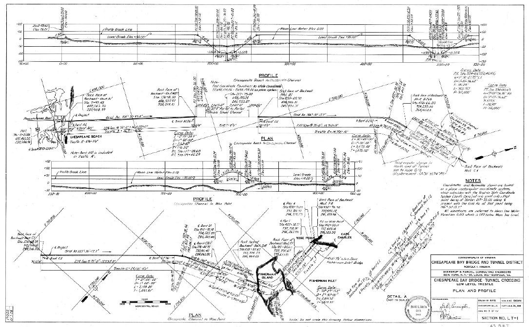
Using information gathered from the site surveyor, we started by creating a Civil 3D site plan. This site plan would be used to plan the initial alignment and footprint of buildings. The site plan was also setup with the project location coordinate system, for use not just by Civil 3D, but also by Revit. Preliminary corridor information about the tunnel and highways was created in separate files. The information was then broken out into smaller units as the project progressed. Civil 3D data shortcuts were used to better manage data.
Key Points: Civil 3D
a. Create site models in both Civil 3D using information from surveyor
b. Alignments, corridors, surfaces in separate files
c. Use data shortcuts to manage data
Revit
The Revit site model was setup by creating a new Revit project from our template and importing the Civil 3D site model. Once the site model was imported, we acquired the coordinate system from the dwg. Each models on own workset, so that it can be turned off prior to loading, to save on load and disk space. Each discipline is then responsible for linking in only the models to which they need design information from. This has helped to keep the size of model files to an acceptable level, while enabling the engineers to see the project, as a whole.
Key Points: Revit
a. Create site models in Revit
b. Create building/structure models, with prototype shapes
c. Bring models into site plan for site orientation and coordinate system assignment
Tunnel — Civil 3D and Revit
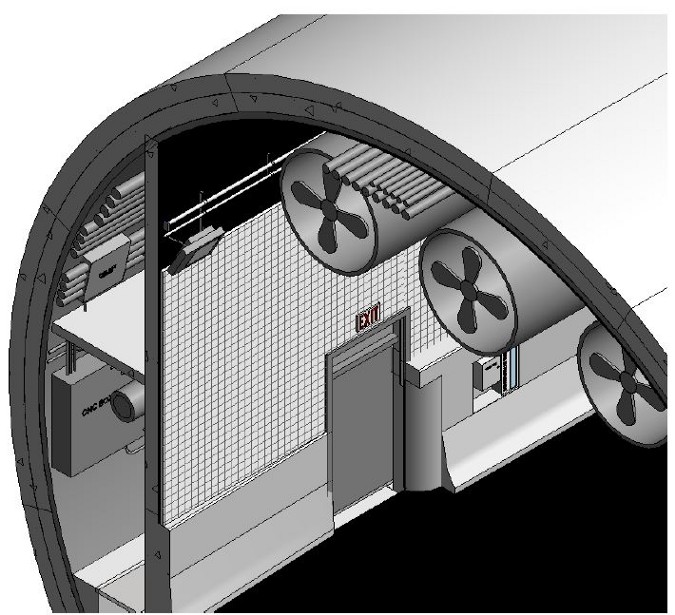
The tunnel itself was built as a corridor within Civil 3D, using custom Civil 3D Assemblies. The sheets drawings would be created using Coil 3D over the course of the project, as we felt it was easier to work with when the time came to create sheet drawings. There were additional coordination models created for discrete areas of the tunnel, to do system coordination.
Ventilation Buildings — Revit
All disciplines associated with the ventilation buildings, were created using Revit. Each discipline was given its own Revit project file to work within. It was initially broached that it would be easier to keep the MEP work all in the same model, but due to the size of the building and number of staff working on each model, it made more sense to keep the trades separate
Highway Creation — Civil 3D
Highway data was created using the corridor creation capabilities of Civil 3D. Design data was then input into the corridor and alignments, so engineers could better see the impacts of their design. We then cut sections through the corridor for further detailing.
Bridge Creation — Civil 3D
Bridge data was also created using the corridor creation capabilities of Civil 3D. We then cut sections through the corridor for further detailing.
Cut and Cover Structure Creation — Revit and AutoCAD
The cut and cover structures were creating using Revit, based on 2D AutoCAD drawings from an initial phase of the project.
Jonathan Servedio is a BIM and technology specialist/lead/manager for the Mott MacDonald North American region, with a focus on Transportation and Water/Waste Water treatment. He has over 15 years of experience working on BIM projects and over 20 years of experience working with CAD. He also helps to implement other types of project technology and is currently responsible for providing BIM/CAD training, standards creation, modeling and drafting support, and plugin/add-on creation.