
Overview
Some people may say that architects and civil engineers are from two different planets. And they’re kind of right. For this reason, getting along can be hard sometimes. Especially when you live and work in two different worlds, or two different coordinate systems at least. But all it takes is a little bit of understanding, some cooperation, and some good software to help us all play nicely together in the sandbox of design.
How is this possible, you say? Well, all it takes are six simple steps:
-
Step 1: Acceptance—Work together to agree on a coordinate system to use
-
Step 2: Initial Handoff—Locate points in Revit and provide an export of a building shell for use in Civil 3D
-
Step 3: Establishing Coordinates—Set real-world coordinate system and establish building corner coordinates and rotation in Civil 3D
-
Step 4: Revit Learns Coordinates—Set real-world coordinates, building location, and rotation provided by Civil 3D in Revit
-
Step 5: Synchronizing the Design Models—Share the building model for use in Civil 3D and the surface model for use in Revit
-
Step 6: Visualizing in InfraWorks—Display the surface and the building model in InfraWorks to create realistic visualizations of the site
In this article, we will discuss these steps and the software involved in each one. By the end, you will understand how coordinates work in Civil 3D and Revit, as well as how a model can be shared between three different software platforms and always fall in the correct location.
Software Overview
We will present a collaborative workflow between both building architects and engineers with civil engineers. To accomplish this workflow we need the following Autodesk software:
- Civil 3D
- Revit
- InfraWorks
- Navisworks Manage
Additionally, you will need access to the BIM 360 Document Management module to gain access to the files stored in the BIM 360 project. In order to access the files stored in BIM 360 Document Management on your local computer, you will need to install the Autodesk Desktop Connector. It can be downloaded free from the Desktop Connector page of the Autodesk Knowledge Network.
In order to have the ability to export Naviswork files (NWC) from Revit, you either need the free Navisworks NWC Export Utility or Navisworks Manage installed. Both of these pieces of software have product years/versions that need to match the Revit product year/version being used. The free Navisworks NWC Export Utility can be downloaded from the Navisworks NWC Export Utility page on Autodesk’s website.
There are a number of options for bringing the building model into InfraWorks. First, the Revit file itself can be directly inserted. However, this insertion can be time consuming and requires you to manually specify a location and rotation for the building inside of the InfraWorks model. An alternative, more efficient way requires the use of Naviswork Manage. With Navisworks Manage, an FBX file can be created from the Revit file that includes the proper coordinate system, location, and rotation.
NOTE: Although BIM 360 Document Management is referenced throughout the presentation, it is only required in order to link the topography from Civil 3D to Revit. The rest of the workflow, including having Revit gather the coordinates from the Civil 3D DWG, can be achieved without the use of BIM 360.
Step 1: Acceptance
Let’s face it. Civil engineers and architects are often very different types of people. So, the first step to getting along is understanding and acceptance of each other and the design and documentation needs of one another.
Dear Civil Engineers,
Architects’ building drawings are rotated so that they fit nicely on a sheet of paper for the creation of construction documents. While engineers often use view adjustments to rotate their sites for the same purpose, the difference is that the architects don’t really (need to) know the direction of North in relation to their building for their documentation purposes. And that’s okay. Also, their drawings are used for the construction of the building itself. It’s really the surveyor’s job to make sure it’s built in the right place.
Dear Architects,
The world is round, and it revolves around the sun, not around your building! I know it’s hard to believe, but it’s true. Your building will be virtually useless if you have no roads, utilities, paths, drainage or other infrastructure around it. This is where the civil engineers come in. They need to make sure all of this ties together. And not just with your building but with all of the other buildings and other fun stuff around it. For this reason, the civil engineers need to be able to know where your building is in relation to all of this infrastructure around it. Hence their need to locate your building and their designs in real-world coordinates.
Locating Buildings in the Real World
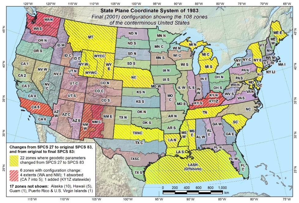
Buildings, bridges, roads, pipes, and other infrastructure items are all located in real-world coordinates based on a system of flat grids. These grids come in many forms. One of the more popular sets of grids used in the United States are called State Planes. As shown in the map below, the country is broken down by state, with many states having more than one State Plane Zone:
Why Is This Necessary?
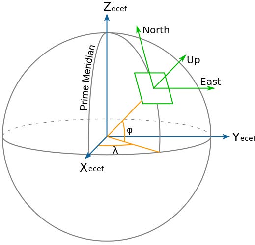
Picture this: You have a basketball in one hand and an 8.5 x 11-inch piece of paper in the other. The basketball represents our spherical planet and the paper represents a flat set of X,Y coordinates.

Can you make that piece of paper fit smoothly on that basketball? The answer is no. Even if you tried to cut it, parts of the paper would still be crinkled while others would overlap. The curvature of our Earth means that having one, flat, X/Y coordinate system will not allow for the accurate mapping of our designs. While Latitude and Longitude values can be used all over the planet, these are angular measurements are difficult to translate quickly into the units we typically use in design for length (meters, feet, etc.). For this reason, the world is broken up into separate grids with unique origins that allow us to map our designs to a curved earth as closely as possible. An illustration of this concept is shown below. The green box shows an example of a small area that has been mapped to a relatively flat square and uses X,Y coordinates.
Civil 3D and Coordinate Systems
Civil 3D supports over 800 different coordinate zones and projections that cover the world. Based on the location of the project, surveyors and civil engineers often agree on a coordinate system that will be used. These coordinates are used for Survey data collection in the field, site layout, utility placement, construction stakeout, and more. For this reason, when a Civil 3D drawing is created, it is often assigned a coordinate system. This does not change the coordinates of objects that are already in the drawing. It tells the drawing which coordinate system is represented by the drawing coordinates to allow for coordinate conversion if/when necessary.
Revit and Coordinate Systems
Revit has three coordinate systems: Internal Coordinates, Project Coordinates, and Shared Coordinates. The Internal Coordinate system was not explained in the presentation for the sake of time but is described below.
Internal Coordinates
This coordinate system is the internal mathematical coordinate system Revit uses to locate all objects within the computer model. This coordinate system has the origin at the point known as the Internal Origin which can be revealed in versions after Revit 2020.2. This coordinate system can cause graphic issues as elements get further away from the origin.
Project Coordinates
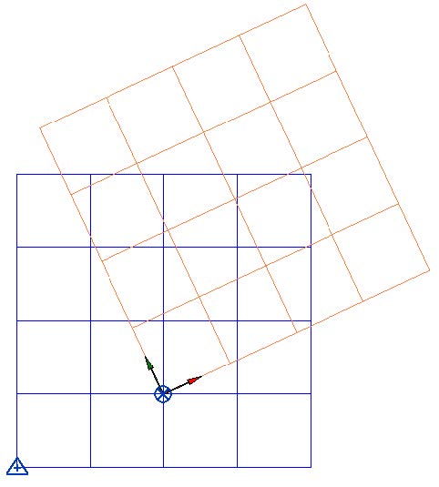
Project Coordinates are aligned so that the Y-axis in plan is oriented to Building or Plan North. This coordinate system has the origin at the Project Basepoint and is used to locate elements relative to the building model. This coordinate system will always have the X and Y axis in the same direction as the Internal Coordinate System. It is best practice to keep this system aligned to the Internal Coordinate system. In other words, keep the Project Base Point and the Internal Origin in the same place! Keeping this system aligned with the Internal Coordinate System will insure graphic fidelity. This is shown as an orange grid in Figure 4 below.
Shared Coordinates
Shared coordinates are used to locate the building in the real world. This system is sometimes referred to as Survey Coordinates, GIS Coordinates, Grid Coordinates, or State Planes. There is no visible origin point for this coordinate system in Revit, which is good due to the graphic fidelity issues associated with distances from the Internal Origin. This coordinate system is established by specifying a relationship between this coordinate system and the Project Coordinate System. The process of specifying the location of this system is covered in this class. This is shown as a blue grid in Figure 4 below. Because this system is located by specifying a relationship between the Project Coordinate System and the Shared Coordinate, it allows the Revit model to exist in multiple Shared Coordinate Systems or multiple locations within the same coordinate system.
Revit Reference Point
Revit has three reference points that have been sometimes noted as Origins. This is not exactly true.
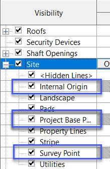
- Internal origin – This is the 0,0,0 of the Internal Coordinate System and was given its own visual point in Revit in release 2020.2. This is the point that can cause the 30-mile radius issues.
- Project Base point – This is the origin of the Project Coordinates. This should be located at the Internal Origin and never moved. This is also the point that stores the relationship between the Project Coordinates and the Shared Coordinates.
- Survey Point – There is a misconception that this is an origin point. It’s not. It is a reference point; it is used to note the location of an existing known point in the real world. It has no control over any coordinate system. It does not represent the origin point of the shared coordinates, and it does not control the elevation of levels (even though Revit’s interface says it does).
Step 2: Initial Handoff (Revit)
Before Revit can coordinate with Civil 3D, or even other Revit Models, there are a few things that need to be determined. The first thing we need to determine is where the building’s datum will be located. In other words, if it is new construction, where is the point that the contractor is going to use to start laying out the structural grid? That might require a conversation with your structural engineer. Once selected, this point will act as the origin of the Project Coordinates. In other words, it will locate the Revit Project Base Point, and in turn, the Internal Origin at this point.
Initial Revit File Setup
Follow these steps to reveal the three-reference points to make sure your building’s datum is located at the Project Base Point and Internal Origin.
1. Open a first floor or site plan view from the Project Browser.
2. Choose Visibility/Graphics from the Graphics panel of the View ribbon tab. The Visibility/Graphic Overrides for <view name> dialog box opens.
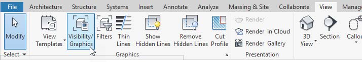
3. Scroll to the site visibility node of the list and click [+] to expand the visibility. The sub list of site categories displays. If you are in a version of Revit after 2020.2, Internal Origin will be listed.
4. Check the Visibility checkboxes for Internal Origin, Project Base Point, and Survey Point from the list of site elements. Click OK to apply the updated visibility and return to your model view.
Alright, so now we’ve established the project coordinates and Project North (Plan North), and we’ve revealed the reference points. At this point, we can start drawing the building, making sure to locate the datum at the Project Base Point. After we get the building outline drawn, we can start the process of coordinating with civil and the outside world.
Alright architects, it’s time for another one of those acceptance moments. We cannot locate the building in the real world without a civil engineer. We may think we know where the building goes, but we don’t always consider site drainage, grade, and infrastructure. So, we might “locate” the building on the site close to where we want. But we need a civil engineer to tell us the actual location. For them to provide us a location of the building, we need to provide them with a plan of the exterior of the building, and if it is new construction, the structural grid.
Export Civil Export Plan View
Follow these steps to export the building footprint from Revit:
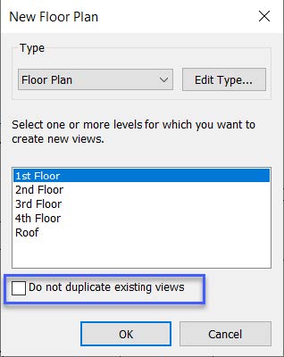
1. Create a new floor plan to generate a Civil Export Plan View. Don’t duplicate this from an existing view.
2. From the Create panel of the View ribbon tab, choose Plan Views ➔ Floor Plan. The New Floor Plan dialog box opens.

3. If your company has a view type for Coordination Plans, select it, otherwise use a standard floor plan. Choose the appropriate level. You may need to uncheck 'Do not duplicate existing views.'
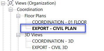
4. Right-click the newly created view within the Project Browser and select Rename from the contextual menu. Enter EXPORT – CIVIL PLAN. To help reduce confusion, change the view Discipline to Coordination. You may also want to move it to a Coordination section in your Project Browser.
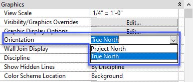
5. In the Properties of the view, change the property Orientation to True North.
6. Open the Visibility/Graphics dialog box from the Ribbon (see Figure 5), or by entering VV on your keyboard. The Visibility/Graphic dialog box opens allowing you to turn off the elements you do not want to see.
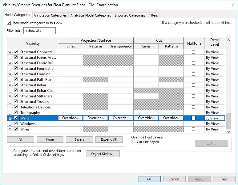
7. Click the All button at the bottom of the Visibility/Graphic dialog box to select all rows. Uncheck the visibility of all modeled objects. Click “None” to unselect all rows.
8. Select the checkboxes next to Walls and Doors and the three reference Points (Internal Origin, Project Base Point, and Survey Point) found as sub categories under Site. The visibility of all modeled objects except for walls, doors, grid lines, and the three reference points should be turned off. Click OK.
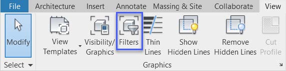
9. From the View Ribbon tab, choose Filters from the Graphics panel to begin creating a filter to hide the interior walls and doors; displaying only the exterior walls and doors for your project. The Filters dialog box opens.
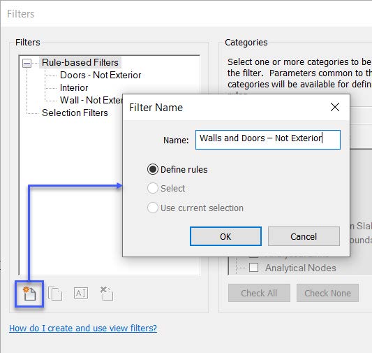
10. Select the New button from the bottom left corner of the Filters dialog box, as show in Figure 13. The Filter Name dialog box opens.
11. Enter a name for your filter, Walls and Doors – Not Exterior in this example, select the Define Rules radio button, and click OK to create the filter.
12. Choose Walls and Doors from the Categories group in the center of the Filters dialog box. It’s important to note, for this to work correctly, the function parameter of each wall type and door type in your model must be appropriately designated.
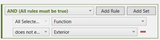
13. Configure the Filter Rules group on the right of the Filters dialog so that the parameter is set to Function, the operator is set to 'Does not equal,' and the value is set to Exterior. Refer to Figure 14 below.
14. Open the Visibility/Graphics dialog box (type VV or VG on the keyboard, or see Figure 5) to apply this filter to your view.
Want more? Download the full class handout to read on.
Nick Sipes has over a decade working in the design and construction industry. For seven years, he worked for a major global Architecture firm in their interior design group where he specialized in corporate offices and government facilities. Following his efforts there, he transitioned to a small Maryland Architecture firm where he became their BIM champion by working to migrate them from AutoCAD to Revit. For the last 3+ years, Nick has been an applications specialist at CADD Microsystems focusing on BIM-related workflows using Revit, Dynamo, and BIM 360. He has presented at several Revit User Groups on the East Coast and the Director of the BIMxt Network, a live online grouping discussing all things BIM in the industry.
Marissa Gagné is the practice manager for Civil and Infrastructure at CADD Microsystems. Marissa graduated from Virginia Tech with bachelor's and master's degrees in Civil Engineering. She has been working with Autodesk products for over 25 years, specializing in the civil and GIS solutions. She has worked for a number of reputable civil firms in Virginia providing CAD support to transportation, utility, land development, mapping, and GIS projects. At CADD Microsystems, Marissa's responsibilities include managing the Civil team, performing product demonstrations, teaching classes, giving seminars and workshops, and performing consulting for many Autodesk products such as Civil 3D, Land Desktop, Map 3D, and Raster Design.